Light mask calibration for DLP and LCD 3D Printers
In this article we propose an easy and relatively quick method to calibrate the light intensity of your LCD/DLP/SLA printer.
The light intensity of a DLP projector lamp or LCD backlight is never perfectly uniform and will usually be higher in the middle of a build platform. In order to correct for this we need to map the light intensity and dim the bright spots such that each part of the build table receives the same amount of light. This usually requires a precise light intensity measurement setup, and this process can be quite tricky.
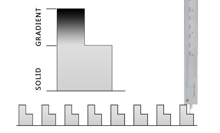
We present a very simple strategy that does not require an extra sensor for this calibration; A grid of blocks is printed which, starting from halfway, are printed with a gradually darker color. Effectively a darker color just means that those pixels are turned off for a longer period of time in each refresh period. Depending on the light intensity in the corresponding part of the build table the darker layers will start failing at different heights. If we precisely measure the height of each block we can accurately map the intensity and generate a corresponding correction map.

Figure 1: Basic layout of the blocks on an example build table
We assume that the layer exposure time has been chosen approximately based on previous prints or the material specifications. This does not have to be exact but should not be more than double the minimum exposure time; we use a gradient from full white (255) to half white (128). Also it should be long enough that all solid bases form properly. If all blocks are fully built the exposure time should be reduced by at least 50%.

Figure 2: Layer buildup and measuring method
In order to calculate the (full scale) color value at which layers fail we first compare the height of each block to the total block height:
Cfail = (Htotal-H)/Htotal * 128 + 128;
The block with the lowest failure color value is the weakest spot. (Shortest block) To calculate the correction map, we next divide each failure color value by the maximum failure color found.
CMaskValue = Cfail / Cmax * 255;
By interpolating these calculated values, a smooth correction map can be generated. This map can then be multiplied with all slice images for that printer.
NB: This calibration is light source specific, if you replace a lamp in your DLP system you will need to recalibrate. Also, over time lamps can develop different emission patterns and will need to be recalibrated, this is especially true for non-led lamps.
You can use Formware3D to export the columns to print for you in the correct gradient as well as export the light mask directly to .png

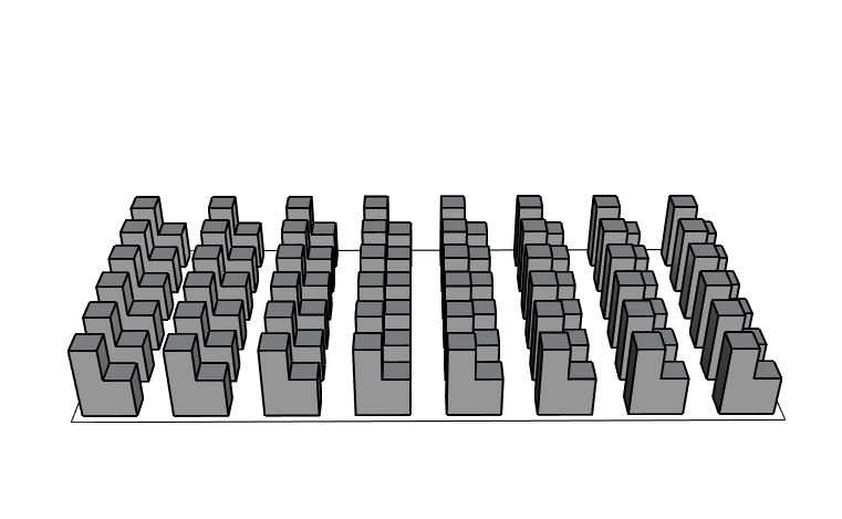
Figure 3: 3D View of the layout we used.

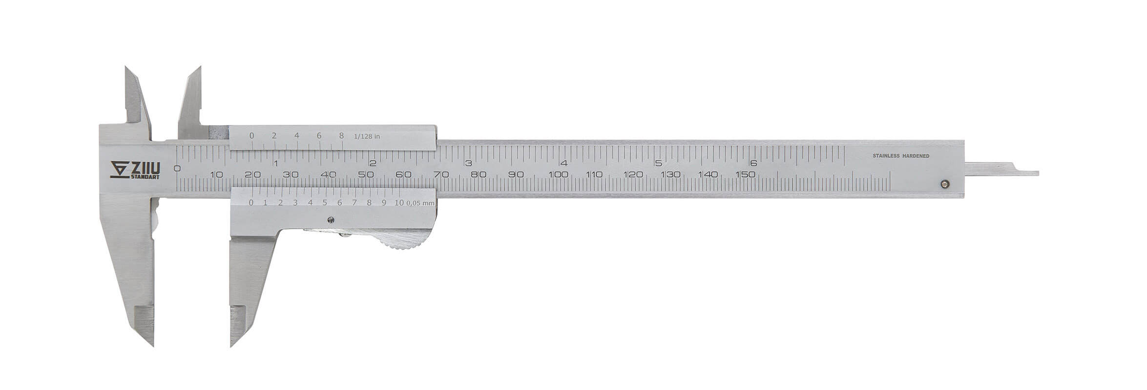
Figure 4: The depth gauge of an analogue caliper can be used to measure the columns quickly.